Dimensions and Project Format

  • The size of the use is determined by the cutting line. The use can have any shape.
  • The project should include two matched files:
  • File with graphics - enlarged by the required bleed.
  • File with cutting and creasing lines - a separate page with cutting and creasing lines precisely matched to the graphics.

For printing uses of any shapes, the bleed is 3 mm on each side. The graphic area must extend beyond the cutting line.

Single Use Project

  • Important objects/information - all important objects (logos, texts, photos) should be at least 3 mm from the planned cutting line.
  • Frames and borders - do not design frames close to the cutting line. The minimum distance is 5 mm to avoid unsightly effects due to cutting tolerance.

Template for Cutting and Creasing

Cutting and Creasing Lines

  • Cutting lines should be designed as hairlines in red color.
  • Creasing lines should be in yellow color.
  • The cutting line must be a single, closed curve without duplication or overlapping other lines.

Minimum Rounding Radii for Cutting Lines:

  • 1.5 mm - for self-adhesive films.
  • 2 mm - for cartons up to 0.4 mm thick and decorative papers.
  • 3 mm - for cartons thicker than 0.4 mm.

Internal Cutouts

Elements cut inside the use must be at least 5 mm away from the external cutting line.

Optimization Tips

  • Avoid excessive number of vertices in cutting lines - this may slow down the plotter's work.
  • Use rounding instead of sharp angles whenever possible.
  • Avoid overly complex shapes: Cut elements should not be too small or very complex to avoid problems with project execution. If the complexity of the cutting curve causes the plotter to work too slowly or prevents order execution, we reserve the right to reject such a project or change the price.

Cutting Tolerance

The fit of the print and cutting edges may vary by ±1.5 mm.

File Saving

The file with the cutting grid should be attached to the print file as the last page in a multi-page file. If files are sent separately, their names must clearly identify the content.

Project Dimensions

Working Area

Projects for die cutting (cutting, creasing lines) must fit within a rectangle with a maximum dimension of 300x470 mm.
Bleeds may extend beyond this area.

Bleeds

The minimum required bleed is 2 mm on each side.

Project Format

Files Required for the Project

The project must include:

  • File with graphics - enlarged by the required bleed.
  • File with cutting and creasing lines - prepared according to guidelines.
  • An additional file with an enhancement mask (e.g., UV varnish, Liquid Gold, Liquid Silver) if the project contains such elements.

Single Use

  • The use can have any shape.
  • All important objects should be at least 3 mm from the cutting line.
  • It is not recommended to design frames, borders, or other elements close to the cutting line - the minimum distance is 5 mm to avoid unsightly effects.

Template for Die Making (for die cutting)

Cutting and Creasing Lines

  • Cutting lines: thin (hairline) in red color.
  • Creasing lines: thin (hairline) in yellow color.
  • Minimum distance between cutting and creasing lines: 4 mm.

Design Rules

  • Cutting and creasing lines should form closed curves if possible.
  • Avoid duplicating or overlapping cutting and creasing lines.
  • Too small or complex elements may prevent die making, resulting in project rejection.

Cutting Precision

The fit of the print and cutting edges may vary by ±1.5 mm.

File Saving

  • The project must be prepared in vector form.
  • Preferred formats: PDF or CDR (vector graphics).
  • The file with the die cutting template should be attached to the print file as the last page in a multi-page file. If files are sent separately, their names must clearly identify the content (“print”, “enhancement”, “die cutting”).

Important Notes

  • In case of technical issues related to the project (e.g., shape complexity), D&D reserves the right to change the price or reject execution.
  • You don't have to worry about preparing the project for die making - files are double-checked with us to ensure their correctness.
  • When reordering, you do not incur the cost of die making, provided that you indicate the use of an existing die in the order (the option “Reorder” is available in the calculator).

Milling allows precise cutting of any shapes in a wide range of rigid materials (from large format printing).

Use Format

  • The maximum use size is 1250 x 2480 mm and is limited by the size of the selected material.
  • The minimum use size is 100 x 100 mm.

Project Format

File Structure

  • The file should be single-page and contain only cutting and/or scoring lines.
  • Scoring lines are made with a 90° conical cutter - they facilitate material bending (only tubond).
  • Lines must be visible and moved to the top of the project layers.

Use for Cutting

  • Fill areas intended for cutting with 100% Cyan color (for the operator to distinguish the use from waste).
  • Mark cutting lines with red hairline color.
  • Mark scoring lines with yellow hairline color.

Space Between Elements

  • If there are multiple cut elements in the file, cutting lines must be at least 10 mm apart.

Project Direction

  • Always design as the front of the use, which is important for single-sided materials and during scoring.
  • Do not send projects in mirror image.

Recommendations for Cutting and Scoring Lines

  • Cutting lines must be closed curves.
  • Avoid overlapping cutting lines.
  • Use straight lines where possible.
  • Minimize the number of vertices - use only as many as necessary to define the curve.
  • Connect lines, creating long segments instead of many short ones.

Material Recommendations

Cutting and scoring depending on the processed material is performed using two technologies: knife or cutter. To achieve a precise effect, consider the specifics of processing for the given substrate and apply appropriate markings in the production file.

MaterialCutting
Technology
Minimum Rounding
Radius (R)
Internal
Vertices
External
Vertices
PCV 2-3 mmKnife6 mmAllowedAllowed
Kappa 5 mmKnife10 mmAllowedAllowed
Kappa 10 mmKnife15 mmAllowedAllowed
Tusand 10 mmKnife15 mmAllowedAllowed
OthersCutter4 mmNot AllowedAllowed

Note: Preparing cutting lines not in accordance with the above recommendations may result in jagged edges.

Notes:

  • Fitting tolerance - the fit of the print and cutting edges may vary by ±1.5 mm.
  • Project complexity - if the project is too complex or not optimally prepared, significantly extending the plotter's work time, we reserve the right to change the price. The client will be informed before order execution.

File Saving

The file with the cutting/milling grid should be attached to the print file as the last page in a multi-page file. If files are sent separately, their names must clearly identify the content.

CO2 laser cutting allows precise cutting and engraving in a wide range of materials within a limited working area.

Working Area

  • The maximum working area is 600 x 457 mm.
  • The project size cannot exceed this area.

Cutting Lines

  • Cutting lines should be designed as hairline in magenta color (100%).
  • In CorelDRAW (if available), disable Color Management in the Tools menu.

File Saving

The file with the cutting grid should be attached to the print file as the last page in a multi-page file. If files are sent separately, their names must clearly identify the content.

File Formats

  • preferred - PDF
  • accepted - CDR

Fitting Tolerance

  • The fit of the print and cutting edges may vary by ±1.5 mm.

Notes

  • Laser cutting allows obtaining a transparent, mirror-like surface, but it is not perfectly smooth as in diamond milling - small irregularities resulting from the material melting process may be visible.
  • In the case of complex shapes or suboptimally prepared files, which extend the plotter's work time, we reserve the right to change the price. The client will be informed before order execution.

Cutting rectangular uses to size is done using two methods: manual knife trimmer or circular saw with fine teeth.

Knife Trimmer

This tool resembles a large knife guillotine cutting system. It operates on the principle of a sliding blade that cuts the material with one smooth motion. It is mainly used for precise trimming of thin materials such as paper, foil, thin cardboard, or plastics.

Circular Saw with Fine Teeth

This cutting tool is equipped with a disc with numerous fine teeth. It is mainly used for cutting thicker materials such as composite panels, thicker cardboard, or materials with greater rigidity.

Both methods leave visible marks on the side edges.

If you want perfectly smooth edges, choose diamond milling, which ensures the highest precision and smoothness of finish.

Standard Products

  • For products such as folded leaflets, folders, etc., creases are predefined, and the file should be prepared according to the dedicated template.
  • Templates for individual products can be downloaded from individual calculators

Custom Works

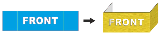
For creasing, perforating, or folding custom projects (not defined in templates), you should:

  • Add a detailed description of the crease location and folding direction in the notes when placing the order.
  • Folding directions may include:
    • V - folding in half.
    • C - folding in "C - inward".
    • Z - folding in "accordion".
  • If possible, crease locations should be marked with a thin yellow line at the edge of the use and/or on the bleed.

Creases in Plotter-Cut Works

  • For works of any shapes cut by plotter, both creasing and cutting lines should be included in the project grid.
  • Detailed guidelines can be found in the Help section Plotter Cutting

Note

Unlaminated paper with a weight of 250-350 g/m² may crack on creasing lines. The effect is particularly visible on dark colors. To avoid this, lamination is recommended.

Drilling holes is a bookbinding process in which holes of a specified diameter are made in printed materials. This service is particularly useful for projects such as calendars, tags, labels, catalog cards for folders, or other materials requiring binding or hanging.

How to Mark Hole Drilling Locations?

  • Marking: Use a small dot in red color (or another color contrasting with the background) with a maximum diameter of 2 mm.
  • The location of the holes should consider the material's strength - holes should not be placed too close to the edge.

Additional Tips

  • If you have questions about preparing the file for hole drilling, contact us - our specialists are happy to help.

To measure the length of a curve line, download the overlay for CorelDRAW™ from our website:
Download file: DDCorelMacro.gms

The overlay works in all versions of Corel starting from CorelDRAW™ 10 onwards.

To add the module to the program, copy it to the ..\Draw\GMS folder located in the folder where CorelDraw™ is installed. With typical settings, it should be: “C:\Program Files\Corel\Corel Graphics 12\Draw\GMS"

In CorelDraw X8, the file should be uploaded to “C:\Users\{username}\AppData\Roaming\Corel\CorelDRAW Graphics Suite X8\Draw\GMS".

Folder naming may vary depending on the version of Corel and the operating system. 

Then, launch CorelDRAW™ and select Tools -> Customization from the menu. The “Options” window should appear on the screen


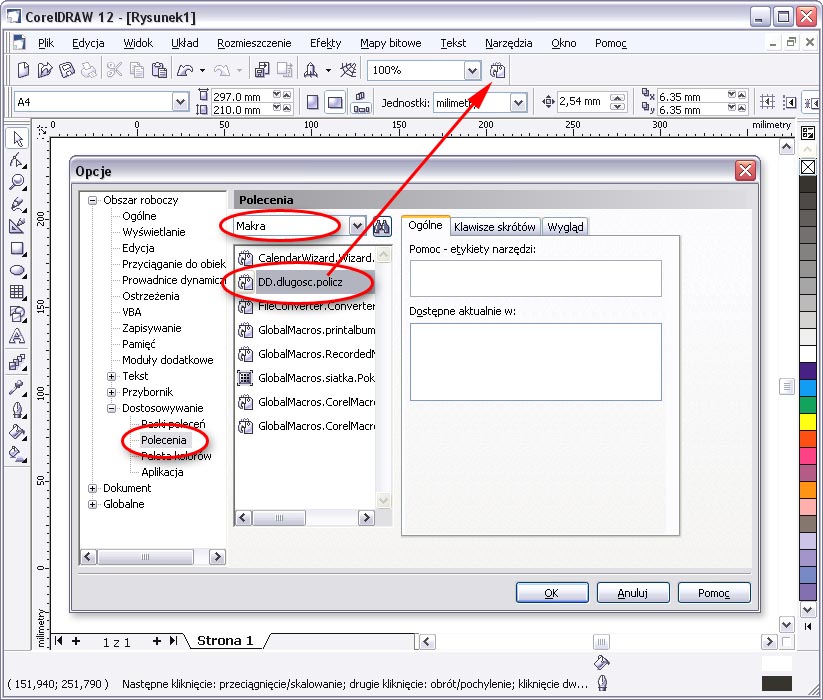
According to the marked fields in the above figure, select Commands from the list of options, then choose Macros from the drop-down menu. Find the DD.dlugosc.policz macro in the list of available modules. To add a button with our macro to the list of buttons, “drag and drop” the selected macro to the button bar and drop it there. (red arrow in the figure) 

To calculate the cutting line length, select all cut shapes and click the newly added button. 

If you do not have the appropriate version of Corel, the length can be measured with any program that has functions for measuring curve length. The length should be provided in millimeters.
If there is no appropriate software, you can print the cutting lines on any printer at a known scale and manually measure the line length using a ruler, compass, or thread, then multiply by the known scale factor. This approximate value should be entered into the calculator, and our employee will correct it after checking the length in the program.